
How to Remove a 2 Post Car Lift: Practical Teardown Guide for 2026
Learn how to remove a 2 post car lift safely with this practical shop teardown guide updated for October 2026.
 By Emily Markham
Updated October 9, 2026
By Emily Markham
Updated October 9, 2026

Garage bay reconfigurations, workshop relocations, and facility upgrades frequently require taking down massive pieces of automotive equipment. When planning how to remove a 2 post car lift, vehicle hobbyists and shop owners must organize every phase around structural balance and stored mechanical energy. Two-post surface-mounted lifts rely on heavy upright steel columns, tensioned wire ropes, and pressurized fluid circuits that demand controlled disassembly to avoid personal injury or property damage. Rushing the process without proper rigging equipment can lead to tipping columns or sudden carriage drops.
Before unbolting a single baseplate nut, you should understand how column balance interacts with carriage positioning, hydraulic circuits, and concrete foundation fasteners. Following an orderly teardown sequence preserves the structural integrity of your columns and hydraulic power units, making reinstallation or sale much easier down the road. Reviewing our hydraulic car lift guide provides helpful perspective on fluid power dynamics and standard operating pressures before you begin cracking fittings loose in your garage.
| Award | Product | BJL Score About BJL ScoreThe BJL Score is our own rating from 0 to 10, based on performance, design and build, ease of use, and value. It reflects independent research and is never influenced by manufacturers, retailers, or affiliate commissions. Learn more › | |
|---|---|---|---|
| Best Overall |
ME 11000lbs Lifting Capacity 2 Post Car Lift 2
|
9.2/10 | Buy |
| Best Value |
 WEIZE 11000lbs Two Post Car Lift
|
9.1/10 | Buy |
| Best Budget |
 KATOOL 1100lbs 2 Post Car Lift Truck Clear Floor
|
8.9/10 | Buy |
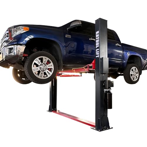 KATOOL 2 Post Lift 4.0HP 12000lbs Single Point
|
8.9/10 | Buy | |
| Best Premium |
 Weize 2 Post Automotive Car Lift
|
8.8/10 | Buy |
 KATOOL Single Point Lock Release 12000lbs Lifting
|
8.4/10 | Buy | |
 KATOOL 12000 lbs Extra Height 167inch 2 Post Lift
|
8.3/10 | Buy | |
 ME 11000lbs Double S Design 2 Post Lift Car Lift
|
8.1/10 | Buy |
Step-by-Step Two-Post Automotive Lift Removal Process
Dismantling a heavy two-post vehicle hoist is essentially the reverse of the installation procedure, but with several critical safety hazards introduced by gravity and structural instability. Once you begin unfastening crossbeams and anchor studs, the individual components lose their mutual rigidity and can become tipping hazards. Working with a dedicated helper, adequate overhead rigging, and the correct mechanical tools ensures the entire teardown proceeds safely and smoothly from start to finish.
Essential Safety Precautions and Pre-Disassembly Equipment Staging
Safety during a lift teardown begins with complete electrical isolation. You must disconnect the power source at the dedicated breaker panel before touching any wiring on the hydraulic power unit. Commercial and residential units typically utilize 220V single-phase electrical lines on 20A or 30A breakers, which present serious shock hazards if left energized. Implement a lockout tagout protocol to ensure nobody accidentally flips the breaker back on while technicians disconnect the motor wiring.
Equipment staging is equally vital before loosening any structural fasteners. You will need a hydraulic shop crane or engine hoist rated for at least two tons, heavy-duty nylon rigging straps, an adjustable ladder, line wrenches, and an oil drain container. Standard two-post lifts with capacities ranging from 11,000 lbs to 12,000 lbs, such as those manufactured by KATOOL or WEIZE, feature individual steel columns that weigh between 700 and 1,100 pounds each. Attempting to balance or catch components of that mass by hand is dangerous and should never be attempted.
Personal protective equipment should include steel-toe work boots, heavy leather work gloves, and impact-resistant safety glasses. Hydraulic lines can retain residual pressure, which may spray atomized oil toward your face when cracked open. Ensure the surrounding garage floor is completely swept and free of oil slicks, hand tools, or trip hazards before you begin maneuvering heavy steel assemblies.
Depressurizing the Hydraulic Circuit and Draining Hydraulic Oil Safely
Stored hydraulic pressure must be relieved before breaking open any fluid lines or hose fittings. With electrical power locked out, depress the manual lowering valve lever on the hydraulic power unit for several seconds. This allows fluid trapped between the pump check valve and the cylinder bases to drain back into the reservoir. Verify that both lifting carriages sit completely flat against their mechanical bottom stops so no fluid remains under load.
Place a clean drain pan beneath the pump reservoir before loosening the tank drain plug or removing the breather cap. Most two-post power units hold approximately three to four gallons of AW-32 or AW-46 hydraulic fluid. Siphon or drain this fluid into sealed storage jugs for recycling or reuse, taking care not to spill oil onto the concrete floor. If your lift uses a 3HP or 4HP motor unit, handling the reservoir when empty significantly reduces the total weight you must lift off the column bracket later.
Once the tank is empty, use two flare nut wrenches to carefully loosen the hydraulic hoses connecting the power unit to the cylinder bases. Hold the stationary bulkhead adapter with one wrench while spinning the hose swivel fitting with the second wrench to prevent twisting the rigid steel lines. Immediately cap or plug all open hose ends and cylinder ports with plastic hydraulic caps to keep dirt out of the system and prevent fluid drips.
Disconnecting and Removing the Swing Arms and Restraint Gears
Removing the four swing arms reduces carriage weight and eliminates awkward swinging appendages that complicate column handling. Begin by raising each arm slightly off the floor using wooden blocks if needed to access the arm pin retainers. Modern two-post hoists utilize vertical steel pivot pins secured by snap rings, cotter pins, or heavy hex bolts at the carriage hinge points. Remove the retaining hardware from the first arm assembly while supporting its outer end.
Drive the pivot pin upward or downward according to the manufacturer design using a brass punch and hammer. Once the pin clears the carriage hinge ears, carefully slide the swing arm assembly outward. Two-stage and three-stage telescoping arms for 11,000 lb and 12,000 lb capacity hoists are constructed from thick tubular steel and can easily weigh 80 to 120 pounds per arm. Have a second person help support the outer reach of the arm to prevent it from dropping onto your feet.
Inspect and store the automatic arm restraint gears and spring-loaded release pins alongside the corresponding swing arm. These gears keep swing arms locked in position under load and can become bent if dropped onto hard concrete. Label each arm with chalk or masking tape to indicate whether it belongs in the front or rear position, particularly on asymmetric configurations where front and rear arms have different reach dimensions.
Lowering Carriages to Base Stops and Releasing Mechanical Safety Locks
Before touching the equalization cables, you must ensure both carriages rest completely on the column base plates with zero mechanical tension. If a carriage is caught on a safety lock ladder tooth, the equalization cables and hydraulic cylinders will remain under significant mechanical strain. For lifts with single-point safety lock releases, pull and hold the release cable mechanism while visually confirming that the lock pawl disengages from the ladder track.
For lifts featuring manual dual-point lock releases, such as standard entry-level commercial units, both columns have separate mechanical latches that must be manually flipped open. If a carriage is wedged against a lock tooth, you may need to use a portable hydraulic bottle jack placed beneath the carriage to take the weight off the pawl before disengaging it. Once disengaged, lower the carriage smoothly until it rests solidly against the bottom rubber cushions or steel stops.
Home garage owners evaluating broader layout changes can review our residential car lift considerations to compare how different locking mechanisms and clearance dimensions function in constrained workshop bays. Ensuring carriages are completely grounded eliminates potential energy from the system, which is essential before unthreading tensioned cable hardware.
Slackening and Unrouting Steel Equalization Cables
Two-post surface-mounted lifts utilize dual aircraft-grade steel wire ropes to synchronize carriage elevation. These cables run over overhead sheaves or under baseplate pulleys, connecting the underside of one carriage to the top or base of the opposite carriage. Locate the threaded terminal studs where the cables fasten to the carriage crossbars. These studs are locked in place with primary retaining nuts and secondary jam nuts.
Use an open-end wrench to hold the square flats of the cable stud while loosening the jam nut with a deep socket. Back the adjustment nuts down the threads evenly on both columns to relieve cable tension gradually. As the nuts loosen, the equalization cables will develop noticeable slack along their vertical runs inside the column channels. Remove the nuts completely and withdraw the threaded cable end through the carriage mounting bracket hole.
Carefully pull the wire ropes out of the column uprights, guiding them over the pulley sheaves to avoid kinking the steel strands. If your lift features a clear-floor design, you must withdraw the cables upward and across the overhead beam assembly. Coil the cables loosely into diameter loops of at least twenty-four inches to prevent permanent wire deformation. Tag the cables with labels so you know which run belongs to the main power unit side versus the slave column side.
Rigging and Disassembling the Overhead Crossbeam and Limit Switch
Clear-floor two-post lifts feature an overhead structural beam that ties the column tops together and routes hydraulic hoses and cables. In extra-tall models like the KATOOL 167-inch overhead unit, this crossbeam sits well above head height and requires careful rigging before unbolting. Begin by disconnecting the electrical wiring connected to the padded overhead limit shutoff bar. This bar acts as a safety kill switch to prevent vehicle roofs from contacting the steel superstructure.
Position an engine hoist or shop crane directly beneath the center of the crossbeam and secure it using a heavy-duty nylon sling in a balanced basket hitch. Take up slight tension on the hoist boom until the sling supports the deadweight of the crossbeam assembly. Never unbolt overhead beam connections without a mechanical hoist or forklift holding the span, as the beam will immediately drop or rotate once the end fasteners are withdrawn.
With the beam supported, climb a secure stepladder to remove the grade-8 flange bolts securing the crossbeam ends to the column top plates. Once all bolts are removed on both sides, gently lower the shop crane boom while a helper guides the beam ends down between the columns. For floor-plate models that lack an overhead arch, this step is replaced by simply unbolting the steel floor cover plate that spans the drive-through path between baseplates.
Column Rigging, Stabilizing, and Structural Support Before De-Anchoring
Once the overhead crossbeam or baseplate cover is removed, each column stands as an independent vertical cantilever. This is the most dangerous stage of the disassembly process because the columns are top-heavy and held only by concrete wedge anchors. Before loosening a single anchor nut, you must rig an overhead crane or anchor strap to prevent the column from tipping backward or sideways.
Wrap a two-inch wide, multi-ton rated lifting strap around the upper third of the column upright, using a secure choker hitch. Connect the strap to your shop crane hook and elevate the boom until there is moderate upward tension on the column. Alternatively, secure heavy-duty ratchet straps from the top column gussets to structural wall framing or adjacent steel posts to establish multi-directional guy lines that prevent tipping.
At this point, also remove the hydraulic power unit motor and reservoir assembly from its column mounting bracket. Power units weigh around 40 to 60 pounds and stick out laterally from the column face. Removing the unit not only protects the delicate aluminum valve block and electrical switches from impact damage but also centers the column weight distribution for safer tipping and handling.
Extracting or Cutting Concrete Wedge Anchors and Baseplate Shims
Two-post lift baseplates are secured to the shop floor using heavy 3/4-inch concrete wedge anchors embedded several inches into the concrete. Use a high-torque impact wrench or long breaker bar to remove the heavy hex nuts and flat washers from each anchor stud. If the installer used horseshoe leveling shims beneath the baseplate corners to plumb the column, pull those shims out and label their positions for future reference.
Standard wedge anchors cannot simply be pulled straight out of cured concrete because their bottom expansion clips bite into the slab when upward force is applied. If the anchor holes were originally drilled completely through the slab or deeper than the anchor length, you can place a brass punch on the stud top and strike it with a sledgehammer to drive the anchor flush into the sub-base beneath the floor. This is often the cleanest extraction method because it leaves no metal protruding above the slab.
If the hole bottom is solid and the anchor will not drive down, you must cut the exposed stud. After tilting the column away from the anchor footprint, use an angle grinder equipped with a metal cutoff wheel to slice the anchor flush with the floor surface. When evaluating used shop equipment or planning a relocation, our overview of auto shop car lifts details how baseplate footprints and anchor patterns affect garage slab layout decisions.
Controlled Column Lowering, Moving, and Site Transport Logistics
With anchor nuts removed and the crane taking the column weight, slowly tilt the column upright away from the anchor studs. Two workers should steady the baseplate while the crane operator slowly lowers the boom, guiding the column downward in a controlled arc. Keep the column base from kicking out violently across the slick concrete floor by placing a heavy timber block against the bottom flange as a pivot stop.
Lower the column until it rests horizontally across heavy wooden blocks or heavy-duty machinery dollies. Setting the steel structure onto wooden 4×4 blocks prevents metal-to-concrete grinding and provides clearance underneath for forklift forks or lifting straps. Repeat this controlled lowering procedure for the opposite column, ensuring that bystanders remain clear of the descent path at all times.
Transporting two-post columns requires adequate truck or trailer bed length. Standard column assemblies measure roughly 110 inches to over 140 inches long, while extra-tall commercial columns can exceed 160 inches in length. Secure the columns to a flatbed trailer using heavy transport chains or grade-70 ratchet straps. Protect the machined carriage tracks and internal hydraulic cylinders from road debris and weather using heavy tarps during transport.
Repairing Concrete Anchor Holes and Restoring Garage Floor Integrity
After the lift columns are completely removed from the workspace, the concrete slab must be repaired to eliminate safety hazards and restore structural durability. Unfilled anchor holes and severed studs create trip hazards and allow moisture to penetrate into the concrete foundation. Begin by blowing dust, concrete aggregate, and debris out of each anchor hole using compressed air and a stiff wire tube brush.
If anchor studs were cut flush, grind the metal slightly below the concrete grade using a handheld grinding wheel. Fill the resulting cavity with a high-strength, non-shrink structural epoxy or anchoring cement rated for concrete repair. Trowel the patching material smooth and flush with the surrounding floor finish, allowing it to cure fully according to the manufacturer cure schedule before rolling heavy floor jacks or vehicle tires over the area.
If you plan to install another two-post lift in the same garage bay in the future, remember that you cannot drill new wedge anchors into or directly adjacent to old filled holes. Concrete building codes and lift manufacturer engineering guidelines mandate a minimum edge distance, typically requiring new anchor holes to sit at least six inches away from old anchor locations or slab expansion joints. Proper hole filling ensures your concrete foundation retains its compressive strength and remains structurally sound for any future automotive equipment.
About the author
Emily Markham is an automotive aftermarket editor who has covered professional tools, workshop equipment, and the businesses that support vehicle repair since 2019. Her editorial background gives her a practical understanding of how technicians and shop owners evaluate equipment, product value, and long-term support.