
Can You Use a Floor Jack on Gravel Safely? Safety Guide for 2026
Learn if can you use a floor jack on gravel safely with our essential vehicle lifting guidelines and equipment stability advice for October 2026.
 By Peter Nelson
Updated October 11, 2026
Operating automotive lifting equipment outside of a clean shop environment introduces unpredictable mechanical risks that demand extra caution. Residential driveways, unpaved shoulders, and rural properties often leave DIY mechanics wondering can you use a floor jack on gravel safely when an unexpected tire puncture or brake issue occurs. Raising thousands of pounds on shifting aggregate compromises basic stability, creating immediate hazards of equipment slip, uneven settling, and sudden vehicle drop. Understanding how loose stone beds alter hydraulic weight distribution ensures you make informed decisions before positioning your lifting gear.
Hydraulic trolley jacks rely on front steel rollers and rear swivel casters to move forward as the lift arm rotates upward in an arc. When wheels sink into loose gravel, that forward motion locks up and subjects the vehicle lift point to severe lateral shear forces. When evaluating alternatives for uneven ground, exploring whether car ramps are safer than jack stands helps clarify which tools provide the safest elevation for specific repair tasks. Establishing proper ground support protocols keeps your undercarriage protected and prevents severe shop accidents.
| Award | Product | BJL Score About BJL ScoreThe BJL Score is our own rating from 0 to 10, based on performance, design and build, ease of use, and value. It reflects independent research and is never influenced by manufacturers, retailers, or affiliate commissions. Learn more › | |
|---|---|---|---|
| Best Overall |
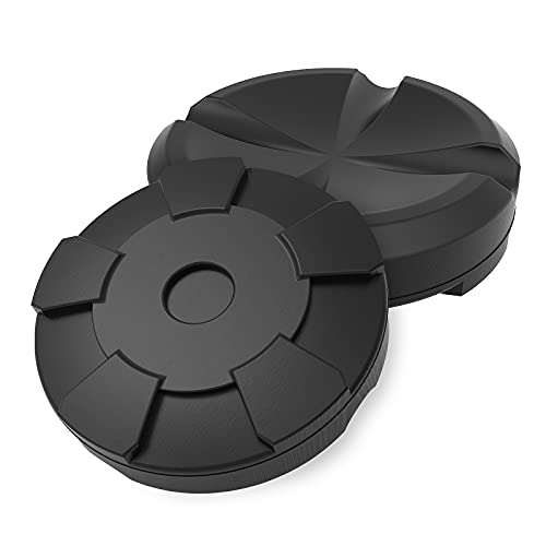
Jack Boss 4.17-Inch Rubber Jack Pads (2-Pack)
|
8.8/10 | Buy |
Jack Boss 4.17-Inch Rubber Jack Pads (2-Pack)
Designed to protect pinch welds and undercarriage finishes, these Jack Boss rubber pads feature a deep center groove and a sturdy 3-ton capacity per unit. They offer an accessible way to cushion vehicle contact points on compatible hydraulic floor jacks.
Pros
- High 3-ton weight rating per pad
- Durable rubber resists crushing and deformation
- Wide groove easily aligns with vehicle pinch welds
- Protects painted chassis parts from metal-on-metal contact
Cons
- Requires measuring jack saddle size to ensure proper fit
- Groove depth may not suit unusually tall pinch welds
- Not intended for heavy-duty commercial vehicles exceeding 3 tons
Engineering Realities and Safety Protocols for Lifting on Gravel Surfaces
Operating a hydraulic floor jack directly on bare, unprotected gravel is unsafe and represents a major hazard for vehicle maintenance. Loose aggregate lacks the structural shear strength required to support high-tonnage point loads, and stones physically block the wheels from tracking properly during elevation. If an unavoidable roadside emergency forces you to lift a vehicle on an unpaved surface, you must engineer a rigid, load-spreading platform beneath both the jack and secondary mechanical supports. Examining the mechanical physics, surface limitations, and hardware solutions helps establish safe protocols for challenging driveway conditions.
The Mechanical Arc and Rolling Geometry of Floor Jacks
Hydraulic trolley jacks do not raise a vehicle in a purely vertical linear path. The lifting arm pivots from a fixed fulcrum pin on the chassis, meaning the lifting saddle travels upward in an arcing trajectory toward the front of the jack. As the saddle elevates, the horizontal distance between the jack chassis and the vehicle contact point shifts continuously. The floor jack must roll forward on its front steel wheels and rear swivel casters to stay centered directly beneath the designated vehicle lift point. If the frame cannot roll, the vehicle moves relative to the saddle rather than the jack moving relative to the ground.
A smooth concrete shop floor provides negligible rolling resistance, allowing the jack to glide smoothly under the vehicle frame during each pump stroke. Loose gravel traps the steel casters, acting as a physical wedge that locks the rolling chassis in place. When the wheels cannot roll forward, the lifting saddle pulls horizontally against the vehicle pinch weld or frame rail. This severe lateral shear force can bend sheet metal, pry the saddle loose from the chassis, or cause the jack to tip over backward. Even a slight angular deviation increases the danger of the vehicle slipping entirely off the saddle face.
Aggregate Displacement and Ground Bearing Capacity
Crushed gravel driveways consist of loose, unbonded stones resting over varying layers of soil, sand, and dust. Cured concrete garage slabs routinely withstand compressive loads exceeding 3,000 pounds per square inch, but uncompacted gravel yields under relatively minor focal stress. A typical passenger car, crossover, or light truck places thousands of pounds of downward force across the vehicle chassis. Raising a single corner or axle concentrates roughly 50 to 60 percent of that gross vehicle mass onto the compact footprint of the floor jack. On soft or gravel surfaces, that dynamic load penetrates downward rather than dispersing across a rigid slab.
The front wheels and rear casters of a standard service jack cover only a few square inches of total ground contact. This tiny contact area generates extreme point pressure that drives the steel wheels deep into the stone layer. Individual stones shift, roll, and crush unevenly beneath the load, throwing the jack off its vertical axis. Uneven settling induces severe side-loading on the hydraulic cylinder, which can score the polished ram, blow internal seals, or cause structural frame failure. Once the jack tilts past a few degrees of plumb, the risk of total structural collapse escalates dramatically.
Stability Hazards of Sinking Jack Stands
Mechanical jack stands present an even greater structural hazard on loose gravel than the hydraulic trolley jack itself. Standard jack stands feature four stamped-steel legs or a narrow perimeter pyramid base with sharp metal feet. These narrow contact points concentrate hundreds of pounds per square inch directly onto the shifting aggregate. As vehicle weight settles onto the stands, individual legs penetrate into the stone layer at inconsistent depths. This differential sinkage causes the center support post to lean away from perpendicular alignment.
A single stand leg sinking just half an inch deeper than the others tilts the entire support column off its center of gravity. Angled loading dramatically degrades the rated holding capacity of a jack stand and creates an immediate tip-over risk. A hydraulic jack is strictly an elevating tool and must never serve as a static load-holding device. Working beneath any elevated vehicle supported by tilted stands on gravel invites catastrophic structural failure. Even minor body movement while turning a wrench can trigger a shift that sends the vehicle off the stands.
Engineering an Approved Sub-Base for Emergency Lifts
Unavoidable rural breakdowns or remote maintenance tasks sometimes force mechanics to work away from paved slabs. Creating a safe lifting zone on gravel requires distributing concentrated point loads across a wide, non-yielding sub-base. The most dependable platform consists of heavy structural carbon steel plate measuring at least 3/8-inch in thickness. A solid steel plate prevents caster penetration and provides a smooth, rigid plane that allows the floor jack wheels to roll freely during arm elevation. This flat metallic surface ensures the jack maintains its engineered rolling geometry throughout the lifting cycle.
Exterior-grade structural plywood offers a practical secondary alternative if heavy steel plate is unavailable. The wooden platform must measure at least 3/4-inch in thickness, remain free of internal voids, and span a minimum footprint of two feet by two feet. Thin composite boards, brittle particle board, or hollow cinder blocks must never be used beneath a jack because they fracture instantly under high point loads. The sub-base must sit completely flat on the aggregate, requiring you to rake away high spots and pack down loose stones before laying the board. Stacking two sheets of 3/4-inch plywood provides additional rigidity when lifting heavier trucks or SUVs.
Surface Staging and Dual-Direction Wheel Chocking
Vehicle stability begins at ground level before the hydraulic saddle makes contact with the chassis. Park the vehicle on the most level section of gravel available to minimize lateral gravitational pull. Shift the transmission into park for automatic vehicles or engage reverse gear for manual gearboxes, and pull the emergency parking brake firmly. Loose stones reduce the tire traction required to hold a vehicle in place while elevating an axle. Relying solely on the vehicle transmission pawl on loose ground can allow the car to roll unexpectedly when elevated.
Heavy-duty rubber wheel chocks must be placed snugly against the front and rear faces of the tires remaining on the ground. Plastic chocks or smooth wood blocks can slide across loose stones under vehicle weight, whereas dense rubber chocks bite into aggregate for superior mechanical grip. Chocking both sides of the unlifted tires prevents forward and backward roll-away vectors as the vehicle balance point shifts during elevation. Never attempt to raise an axle if the opposite tires are parked on a steep incline or slick mud. Securing the remaining tires firmly to the earth provides the necessary anchoring force for a controlled lift.
Protecting Undercarriage Lift Points from Lateral Shearing
Challenging ground conditions amplify the risk of damaging factory lift points and undercarriage components. Factory unibody pinch welds consist of folded sheet metal seams that bend easily when subjected to uneven lateral forces. Bare steel jack saddles focus immense pressure on tiny sections of painted metal, risking cracked rocker panels and fractured seam welds. Integrating a rubber adapter provides an essential mechanical cushion between the steel saddle and the vehicle chassis. This rubber buffer absorbs small angular discrepancies that occur when operating outside of a level shop bay.
The JACK BOSS Jack Pad Universal Large Floor Jack is designed specifically to protect vulnerable pinch welds and frame rails during elevation. This rubber pad adapter measures 4.17 inches in diameter and one inch in thickness, providing a broad load distribution face across standard hydraulic saddles. Its center groove features a width of 0.7 inches and a depth of 0.23 inches, seating unibody pinch weld seams securely without crushing surrounding rocker molding. The sturdy rubber compound resists crushing under working load limits up to 3 tons per pad while gripping both the metal saddle and the vehicle frame to reduce slippage. Using a tailored adapter prevents frame gouging that could lead to rust and structural weakening over time.
Step-by-Step Procedure for Controlled Emergency Elevation
Executing an emergency lift on gravel demands methodical attention to detail at every stage of the process. Clear the designated work area of loose, protruding stones to create a level dirt or gravel bed for your base platform. Lay your thick structural steel plate or heavy plywood sheet over the cleared ground, ensuring the board does not rock or flex when stepped on. Center the hydraulic floor jack on the platform, confirming that all four wheels have sufficient rolling clearance across the surface. Take extra care to ensure the jack chassis has a clear path to roll forward as the arm rises.
Position the saddle directly beneath the manufacturer-specified factory lift point, inserting a slotted rubber adapter to cradle the pinch weld seam. Close the hydraulic release valve clockwise until snug, avoiding excessive torque that could bind the internal valve seat. Pump the jack handle slowly until the saddle contacts the lift point, pausing to check that the saddle is centered before taking on vehicle weight. Elevate the vehicle in short, controlled strokes while continuously observing the jack casters to verify that the chassis rolls forward smoothly without tilting. Stop pumping immediately if you hear the wood splintering or observe the plate sinking into the gravel.
Locking Mechanical Supports and Safety Verification
Hydraulic systems rely on internal rubber O-rings, check valves, and fluid pressure that can fail without warning. Never place your hands, limbs, or torso beneath an elevated vehicle until mechanical jack stands are secured in place. When working over gravel, each jack stand requires its own dedicated structural base plate made of heavy steel or thick exterior plywood. Position the stands beneath reinforced factory frame rails, suspension subframe crossmembers, or solid axle tubes. Avoid placing stands under floorboards, steering linkages, or thin suspension arms that cannot bear the vehicle weight.
Adjust the height of the ratcheting or pin-lock columns to the lowest operational notch that permits necessary maintenance clearance. Turn the floor jack release valve counter-clockwise very slowly using its universal joint mechanism to lower the vehicle onto the stands with micro-metered precision. Verify that the load settles squarely onto the center saddle of each jack stand without driving any corner of the stand feet into the wooden or metal base. Give the vehicle a firm physical push test at the bumper while standing safely clear to ensure structural rigidity before starting work. If the stands shift, wobble, or cause the base boards to crack, raise the hydraulic jack immediately, lower the vehicle to the ground, and rebuild your support base.
Evaluating Service Ramps as a Practical Gravel Alternative
Certain maintenance tasks such as oil changes and underbody fluid inspections do not require wheel removal. Driving onto solid automotive service ramps often provides a far safer elevation alternative on gravel than maneuvering a hydraulic floor jack. Ramps feature broad base footprints that distribute vehicle weight across a much larger surface area than narrow jack casters and stand feet. However, unpaved surfaces present unique hazards for ramps, including sinking corners and sliding ramp bases during vehicle ascent. Uneven ground can cause ramp side rails to dig into stones, twisting the structure out of alignment.
Implementing reliable methods to stop vehicle ramps from sliding ensures that ramp assemblies stay anchored against loose aggregate when tires make initial contact. In rural shops or unpaved driveways, building solid wooden service ramps using tiered solid lumber can provide broad, non-deforming elevation platforms tailored to rough terrain. Service ramps maintain continuous wheel support and eliminate the dangerous lateral arcing forces generated by hydraulic trolley jacks. Always verify that ramps sit flat without gaps beneath their load-bearing rails before attempting to drive onto them. Placing heavy plywood runners underneath the ramps prevents their lower edges from sinking into the gravel.
Dynamic Load Calculations and Tonnage Safety Margins
Understanding the distinction between gross vehicle curb weight and dynamic lifting load is vital when working on unstable ground. A floor jack does not lift an entire vehicle at once, but rather raises a single axle or corner, which accounts for roughly 50 to 60 percent of total curb weight. However, unpaved surfaces introduce shifting balance vectors that can transfer additional weight onto the lifting point if the opposite suspension compresses unevenly. For example, lifting a 4,000-pound sedan requires supporting at least 2,400 pounds dynamically, demanding a floor jack with an adequate working load limit.
Using a 3-ton capacity floor jack provides a crucial safety buffer against unexpected hydraulic overload on uneven terrain. Quality jacks incorporate internal overload bypass valves designed to prevent the ram from extending if the load exceeds rated capacity. On shifting gravel, an undersized 1.5-ton or 2-ton jack operates too close to its mechanical threshold, increasing the risk of hydraulic bypass activation or cylinder seal failure. Selecting equipment with a generous tonnage rating ensures the hydraulic assembly maintains structural rigidity even if ground resistance fluctuates during the lift.
Post-Service Equipment Maintenance and Caster Inspection
Lifting on gravel exposes automotive tools to abrasive dirt, stone dust, and potential structural misalignment. Once your repair is complete and the vehicle rests securely on the ground, inspect your lifting equipment thoroughly before storage. Wipe down the polished chrome hydraulic ram with a clean shop towel to remove grit that could cut internal nitrile cylinder seals. Examine the steel front rollers and rear swivel casters to verify that stone fragments have not wedged into the roller axles or ball-bearing races. Trapped stones can flat-spot steel wheels or jam bearings during subsequent lifts.
Check the jack frame side plates and lift arm pivot pins for any signs of twisting or lateral deflection caused by uneven ground contact. Inspect your rubber jack pad adapters for cuts, deep gouges, or structural tears along the pinch weld groove. Store the hydraulic floor jack in a clean, dry garage with the lift arm fully lowered and the release valve closed to protect the internal seals from atmospheric moisture. Routine post-lift maintenance ensures your lifting tools remain safe, reliable, and ready for future garage service. Proper tool care protects your investment and ensures predictable operation whenever unexpected repairs arise.
Maintaining safety on unpaved surfaces requires respecting the physical limitations of hydraulic lifting equipment and unbonded stone ground. Never take shortcuts by placing bare jack stands or trolley casters directly onto shifting aggregate. Taking the time to establish a wide, rigid sub-base, chocking unlifted tires, and using grooved rubber saddle adapters protects your vehicle investment and keeps you safe during driveway repairs. When in doubt, delaying non-emergency maintenance until the vehicle can reach a solid concrete slab remains the smartest decision a home mechanic can make.
About the author
Peter Nelson is an automotive writer whose published work includes off-road jacks, power tools, vehicle maintenance, and garage equipment. His coverage connects product features with practical applications, helping readers think through equipment choices for everyday repairs, project vehicles, and off-road situations.